- 您现在的位置:买卖IC网 > Sheet目录3886 > PIC16LCE624-04E/SS (Microchip Technology)IC MCU CMOS 1K OTP W/EEPRM20SSOP
1999 Microchip Technology Inc.
DS40182C-page 11
PIC16CE62X
4.0
MEMORY ORGANIZATION
4.1
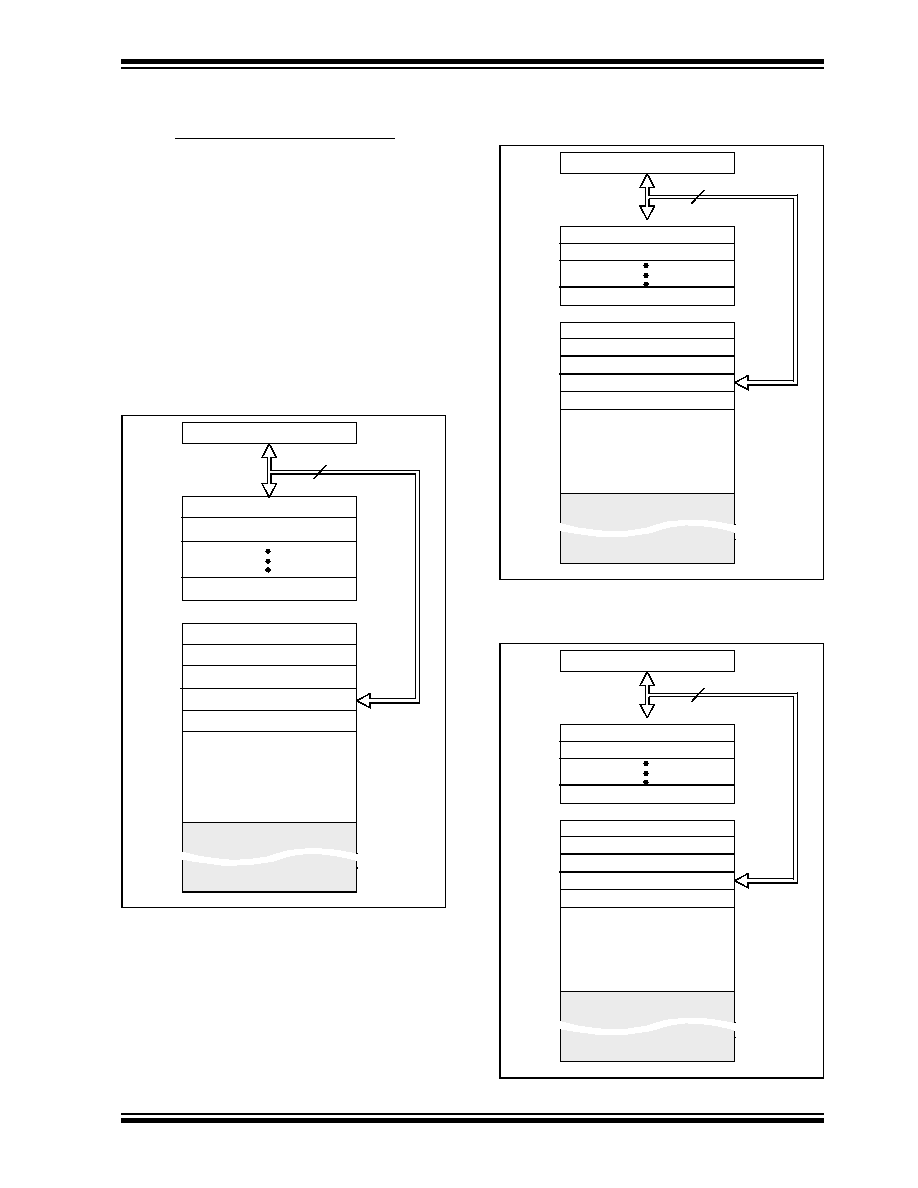
Program Memory Organization
The PIC16CE62X has a 13-bit program counter capa-
ble of addressing an 8K x 14 program memory space.
Only the first 512 x 14 (0000h - 01FFh) for the
PIC16CE623, 1K x 14 (0000h - 03FFh) for the
PIC16CE624 and 2K x 14 (0000h - 07FFh) for the
PIC16CE625 are physically implemented. Accessing a
location
above
these
boundaries
will
cause
a
wrap-around
within
the
first
512
x
14
space
(PIC16CE623) or 1K x 14 space (PIC16CE624) or 2K
x 14 space (PIC16CE625). The reset vector is at 0000h
and the interrupt vector is at 0004h (Figure 4-1,
FIGURE 4-1:
PROGRAM MEMORY MAP
AND STACK FOR THE
PIC16CE623
PC<12:0>
13
000h
0004
0005
01FFh
0200h
1FFFh
Stack Level 1
Stack Level 8
Reset Vector
Interrupt Vector
On-chip Program
Memory
CALL, RETURN
RETFIE, RETLW
Stack Level 2
FIGURE 4-2:
PROGRAM MEMORY MAP
AND STACK FOR THE
PIC16CE624
FIGURE 4-3:
PROGRAM MEMORY MAP
AND STACK FOR THE
PIC16CE625
PC<12:0>
13
000h
0004
0005
03FFh
0400h
1FFFh
Stack Level 1
Stack Level 8
Reset Vector
Interrupt Vector
On-chip Program
Memory
CALL, RETURN
RETFIE, RETLW
Stack Level 2
PC<12:0>
13
000h
0004
0005
07FFh
0800h
1FFFh
Stack Level 1
Stack Level 8
Reset Vector
Interrupt Vector
On-chip Program
Memory
CALL, RETURN
RETFIE, RETLW
Stack Level 2
发布紧急采购,3分钟左右您将得到回复。
相关PDF资料
PIC16F687-I/P
IC PIC MCU FLASH 2KX14 20DIP
PIC16LF1829-I/SO
MCU PIC 14KB FLASH 20-SOIC
PIC16LCE624-04E/SO
IC MCU CMOS 1K OTP W/EEPRM18SOIC
PIC16F1829-I/SO
MCU PIC 14K FLASH 1K RAM 20SOIC
PIC16F685-I/SS
IC PIC MCU FLASH 4KX14 20SSOP
PIC16LCE624-04E/P
IC MCU CMOS 1K OTP W/EEPRM 18DIP
PIC16F689-I/SS
IC PIC MCU FLASH 4KX14 20SSOP
PIC16C54C-04I/SO
IC MCU OTP 512X12 18SOIC
相关代理商/技术参数
PIC16LCE624-04I/P
功能描述:8位微控制器 -MCU 1.75KB 96 RAM 13 I/O RoHS:否 制造商:Silicon Labs 核心:8051 处理器系列:C8051F39x 数据总线宽度:8 bit 最大时钟频率:50 MHz 程序存储器大小:16 KB 数据 RAM 大小:1 KB 片上 ADC:Yes 工作电源电压:1.8 V to 3.6 V 工作温度范围:- 40 C to + 105 C 封装 / 箱体:QFN-20 安装风格:SMD/SMT
PIC16LCE624-04I/SO
功能描述:8位微控制器 -MCU 1.75KB 96 RAM 13 I/O RoHS:否 制造商:Silicon Labs 核心:8051 处理器系列:C8051F39x 数据总线宽度:8 bit 最大时钟频率:50 MHz 程序存储器大小:16 KB 数据 RAM 大小:1 KB 片上 ADC:Yes 工作电源电压:1.8 V to 3.6 V 工作温度范围:- 40 C to + 105 C 封装 / 箱体:QFN-20 安装风格:SMD/SMT
PIC16LCE624-04I/SS
功能描述:8位微控制器 -MCU 1.75KB 96 RAM 13 I/O RoHS:否 制造商:Silicon Labs 核心:8051 处理器系列:C8051F39x 数据总线宽度:8 bit 最大时钟频率:50 MHz 程序存储器大小:16 KB 数据 RAM 大小:1 KB 片上 ADC:Yes 工作电源电压:1.8 V to 3.6 V 工作温度范围:- 40 C to + 105 C 封装 / 箱体:QFN-20 安装风格:SMD/SMT
PIC16LCE624T-04/SO
功能描述:8位微控制器 -MCU 1.75KB 96 RAM 13 I/O RoHS:否 制造商:Silicon Labs 核心:8051 处理器系列:C8051F39x 数据总线宽度:8 bit 最大时钟频率:50 MHz 程序存储器大小:16 KB 数据 RAM 大小:1 KB 片上 ADC:Yes 工作电源电压:1.8 V to 3.6 V 工作温度范围:- 40 C to + 105 C 封装 / 箱体:QFN-20 安装风格:SMD/SMT
PIC16LCE624T-04/SS
功能描述:8位微控制器 -MCU 1.75KB 96 RAM 13 I/O RoHS:否 制造商:Silicon Labs 核心:8051 处理器系列:C8051F39x 数据总线宽度:8 bit 最大时钟频率:50 MHz 程序存储器大小:16 KB 数据 RAM 大小:1 KB 片上 ADC:Yes 工作电源电压:1.8 V to 3.6 V 工作温度范围:- 40 C to + 105 C 封装 / 箱体:QFN-20 安装风格:SMD/SMT
PIC16LCE624T-04E/SO
功能描述:8位微控制器 -MCU 1.75KB 96 RAM 13 I/O RoHS:否 制造商:Silicon Labs 核心:8051 处理器系列:C8051F39x 数据总线宽度:8 bit 最大时钟频率:50 MHz 程序存储器大小:16 KB 数据 RAM 大小:1 KB 片上 ADC:Yes 工作电源电压:1.8 V to 3.6 V 工作温度范围:- 40 C to + 105 C 封装 / 箱体:QFN-20 安装风格:SMD/SMT
PIC16LCE624T-04E/SS
功能描述:8位微控制器 -MCU 1.75KB 96 RAM 13 I/O RoHS:否 制造商:Silicon Labs 核心:8051 处理器系列:C8051F39x 数据总线宽度:8 bit 最大时钟频率:50 MHz 程序存储器大小:16 KB 数据 RAM 大小:1 KB 片上 ADC:Yes 工作电源电压:1.8 V to 3.6 V 工作温度范围:- 40 C to + 105 C 封装 / 箱体:QFN-20 安装风格:SMD/SMT
PIC16LCE624T-04I/SO
功能描述:8位微控制器 -MCU 1.75KB 96 RAM 13 I/O RoHS:否 制造商:Silicon Labs 核心:8051 处理器系列:C8051F39x 数据总线宽度:8 bit 最大时钟频率:50 MHz 程序存储器大小:16 KB 数据 RAM 大小:1 KB 片上 ADC:Yes 工作电源电压:1.8 V to 3.6 V 工作温度范围:- 40 C to + 105 C 封装 / 箱体:QFN-20 安装风格:SMD/SMT